B21, China Town Mall, Midrand


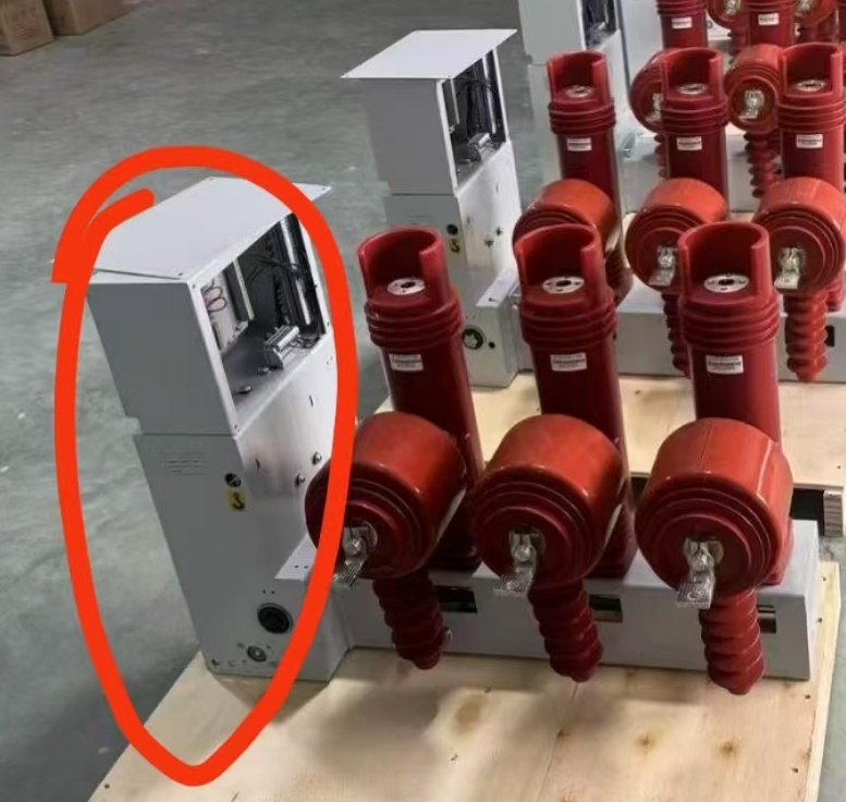
GVS7-24T/630-25 Circuit Breaker+ Micro-Computing Control+ Current Transformer ALL In One System 24kv
Asset finance available
Do you want funding for this equipment?
Afrimart can connect you with trusted funding partners who specialise in asset finance for businesses like yours. Compare options and apply in minutes — final approval is subject to provider review.
Check funding options
Secure & no obligation

Model:
- Section : Electrical & Tools
- Category : Power Supplies
- SKU : 1601266890101

GVS7-24T/630-25 Circuit Breaker+ Micro-Computing Control+ Current Transformer ALL In One System
- Shipping Timeframes: All orders are processed within 2-5 business days (excluding weekends and holidays). After your order has been processed, the estimated delivery time is before 03 Aug, 2026, depending on customs, Please note that due to high demand, some items may experience longer shipping times, which will be communicated at order confirmation email.
- Order Processing Time: Please allow 2-5 business days for us to process your order before it is shipped . Orders placed after 16:00 on Fridays, or during weekends and public holidays, will begin processing on the next business day. Processing times may be extended during peak seasons or sales events.
- Manufacturing Time: Some products needs manufacturing time, the manufacturing process will take approximately 10-30 business days depending on the product. This timeframe may vary depending on the complexity of the product and current demand. but this will be communicated with you during order confirmation.
- Returns and Exchanges: We offer a 30-day return policy for most items. If you are not completely satisfied with your purchase, you may return it within 30 days of receipt for a refund or exchange. Items must be unused, in their original packaging, and accompanied by proof of purchase. Return shipping costs are the responsibility of the customer, unless the item was damaged or defective upon arrival.
1. What is the GVS7-24T/630-25 system?
An integrated 24 kV all-in-one unit combining a vacuum circuit breaker (GVS7 series), a micro-computing protection/control unit and built-in current transformers for measurement and protection functions.
2. What are the primary electrical ratings?
Nominal system voltage is 24 kV. The model designation indicates a rated current of 630 A and a rated short-circuit breaking capacity of 25 kA (consult the datasheet for specific test conditions and alternatives).
3. Which protection and control functions are provided by the micro-computing unit?
Typical functions include phase overcurrent, earth-fault/ground protection, short-circuit protection, inverse/time-overcurrent curves, programmable trip/time delays, automatic reclose, event recording, metering and status diagnostics. Specific functions are configurable via the protection relay firmware.
4. What kind of current transformers are integrated?
Primary-integrated CTs are supplied as part of the all-in-one unit for protection and metering. Standard CT ratio options are available (e.g., 100/5, 200/5, 400/5) and can be customized to project requirements—refer to the order options.
5. Which communications protocols are supported?
Communication options typically include industry-standard protocols such as IEC 61850, Modbus (RTU/TCP) and serial communications. Available interfaces and protocols should be confirmed when ordering.
6. Can protection settings and logic be changed on site?
Yes — the micro-computing controller provides programmable protection settings and logic. Settings are adjustable via front-panel HMI, PC software or remote communication (depending on the chosen interface).
7. Where is this unit intended to be installed?
It is designed for integration into 24 kV switchgear/RMU or substation applications. Installation must be performed by qualified personnel following local electrical codes and the manufacturer's installation manual.
8. What control power does the unit require?
Control power requirements vary by configuration. Common options include DC or AC supplies (for example 24/48/110 VDC or 220 VAC). Confirm the required control-power option in the product datasheet or with the supplier prior to installation.
9. What testing and commissioning is recommended?
Factory acceptance testing is recommended. On-site commissioning should include insulation checks, contact resistance and timing tests, secondary injection tests of protection functions, CT polarity and ratio verification, and coordinated protection setting validation by qualified engineers.
10. What maintenance is required and how often?
Regular visual inspections and cleaning are recommended. Mechanical operation cycles, contact wear checks and electrical tests (trip coil, secondary injection) should be performed periodically—typical practice is visual checks quarterly/biannually and detailed electrical/mechanical tests annually. Follow the manufacturer maintenance manual for exact intervals.
11. What environmental and mechanical ratings does the product have?
The unit is designed for typical utility and substation environments. Specific environmental ratings (operating temperature range, humidity limits, IP degree, altitude and seismic ratings) are provided in the technical datasheet and should be checked for your application.
12. Which standards and certifications does the product comply with?
The product is designed to comply with applicable high-voltage circuit breaker and switchgear standards (for example IEC 62271 series). CE and other regional certifications/options can be provided depending on the model and destination—confirm with the supplier.
13. Are spare parts and accessories available?
Yes. Spare parts and accessories such as auxiliary/contact modules, trip coils, additional CTs, remote communication modules, and control cubicles are available. Contact the manufacturer or distributor for part numbers and lead times.
14. Can the breaker be remotely operated and monitored?
Yes. With the appropriate communication interface and control wiring, the micro-computing control unit supports remote open/close commands as well as status and metering telemetry. Specify required remote-control features when ordering.
15. What warranty and after-sales support are offered?
Standard manufacturer warranty and technical support are provided; exact warranty length and support terms vary by supplier and sales contract. Request warranty details, local service availability and response times from your vendor at purchase.
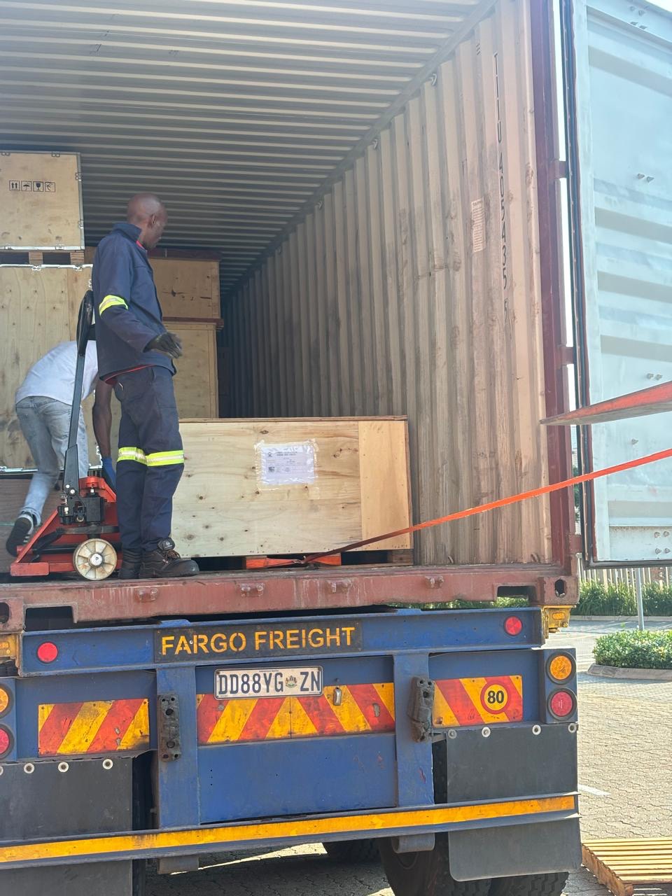
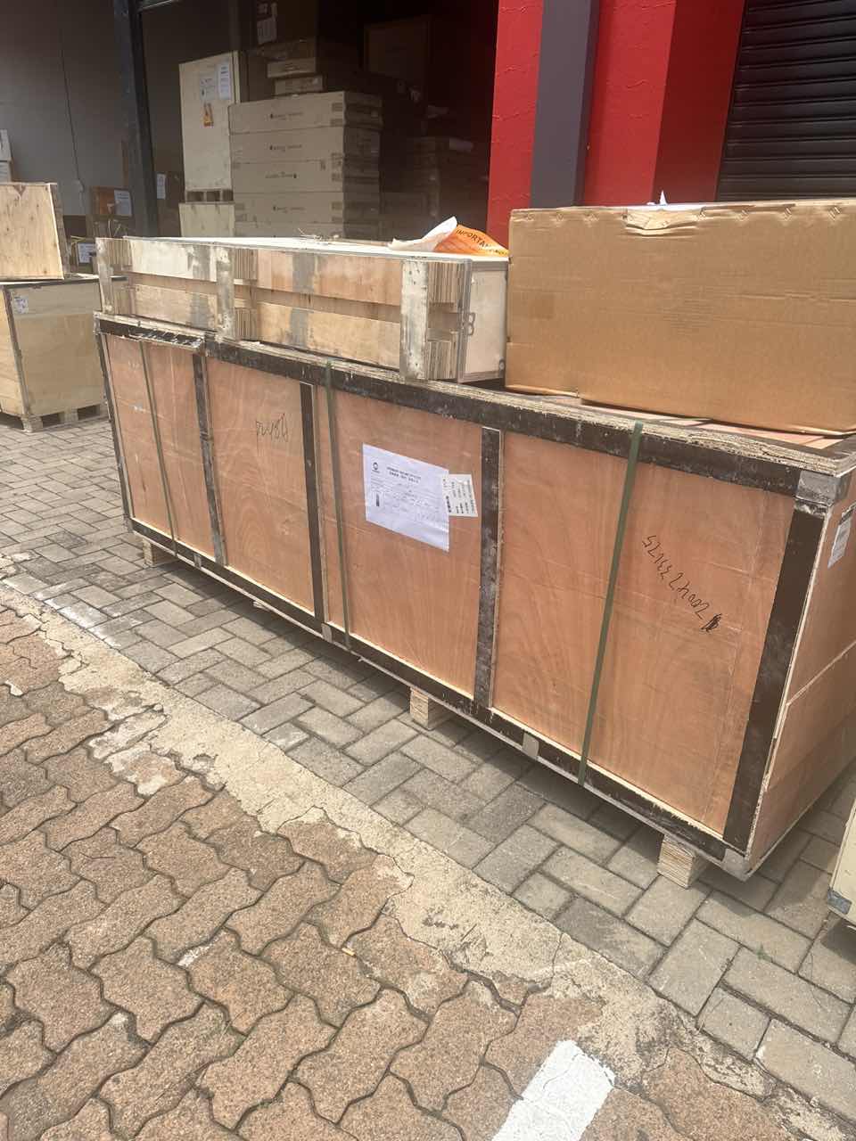
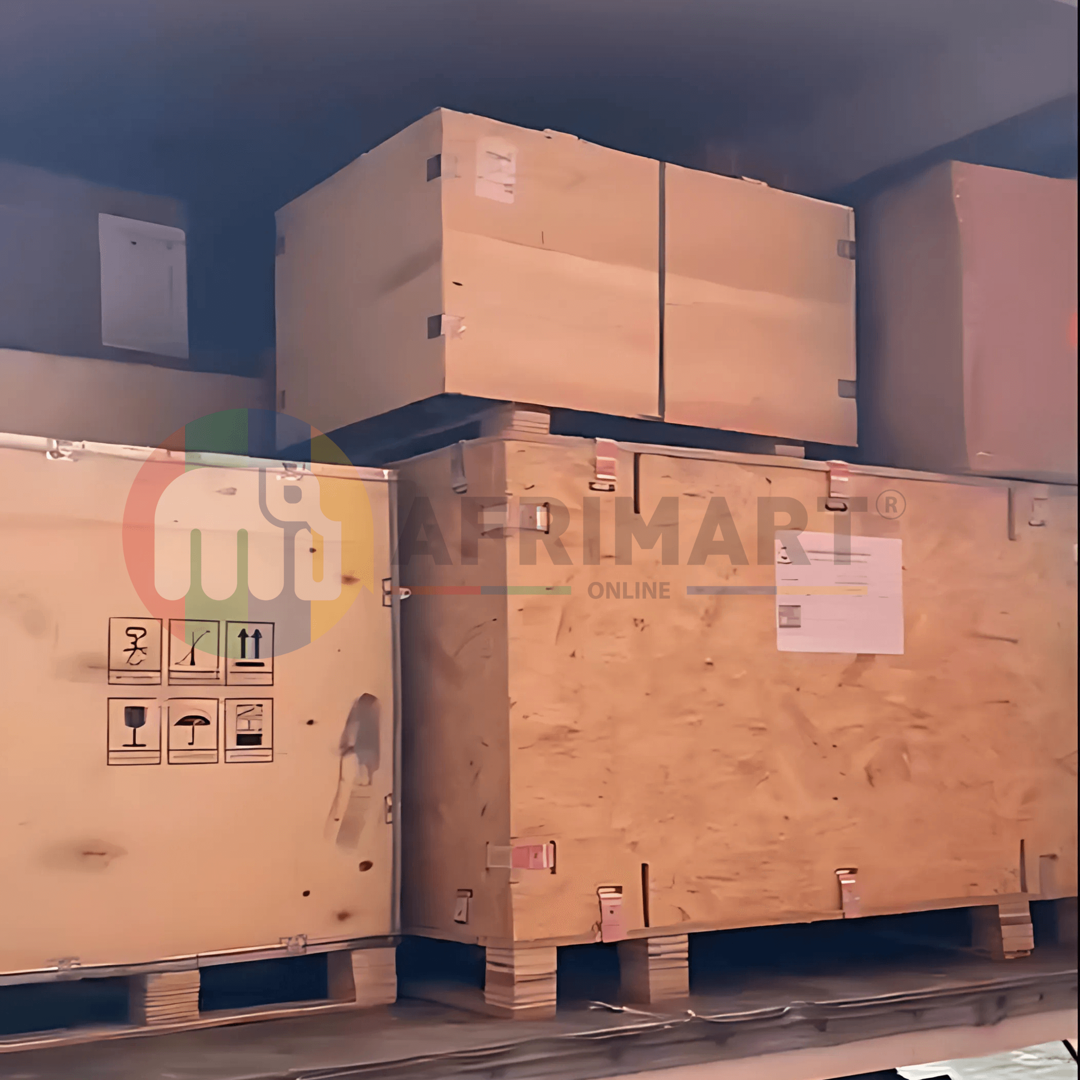
Latest Order Arrivals
Discover our latest orders
12 Heads Embroidery Machine
Toilet Paper Machine Machine

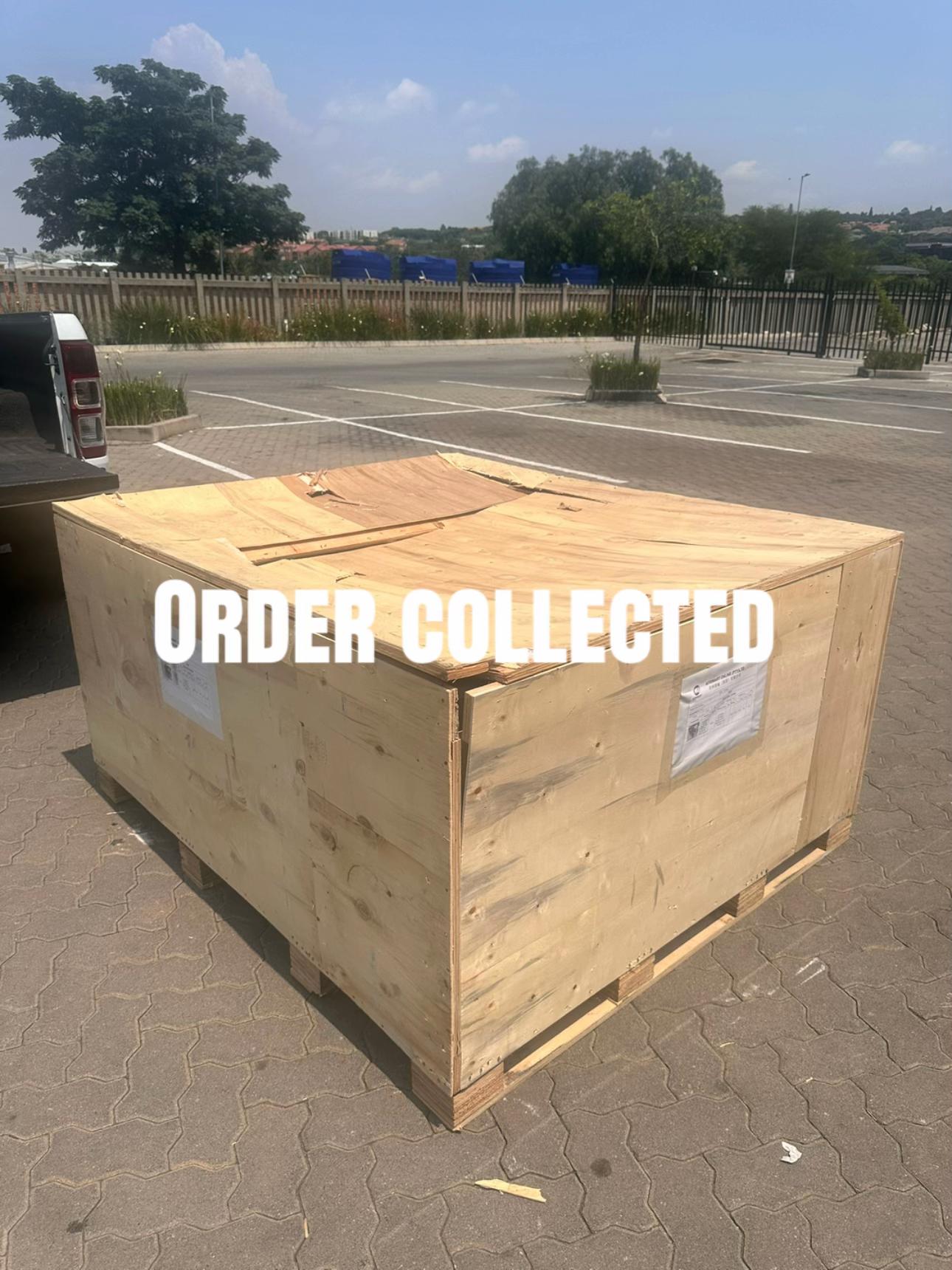
Order Collection
Cross Border Clients
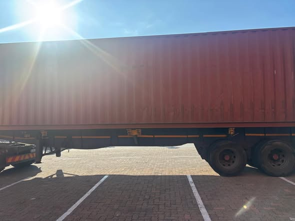
Order cros border countries Collected
Industrial Machine Cllection
Agriculture Processing Machines

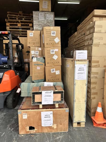
Ready for collection

Water Pump Equipment
Packaging Machine and accessories
Fabrics Manufacturing Equipment
Mining Equipments
Food Processing Machine
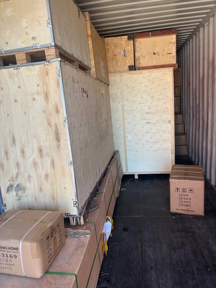
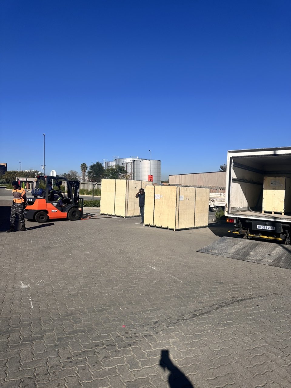
Batch of Orders
Batch of Orders
Latest Orders Labelled
wheel alignment machines
new arrivals
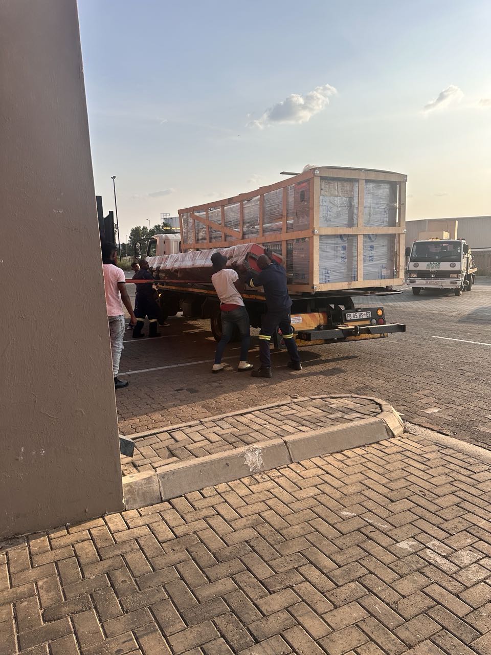
Pre Orders Offloading
Latest Arrivals
Latest Arrivals
Latest Arrivals
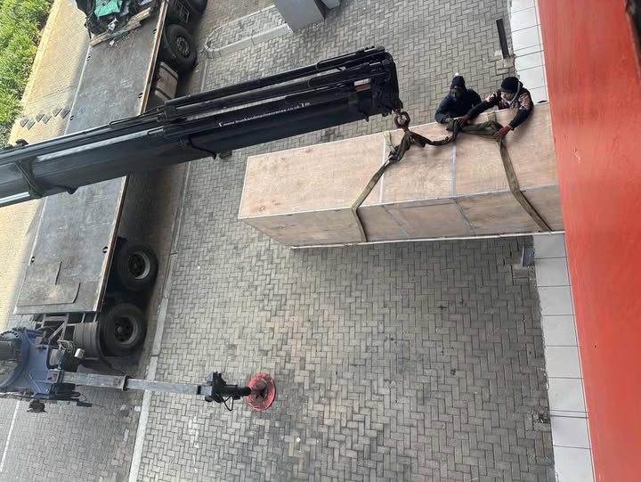
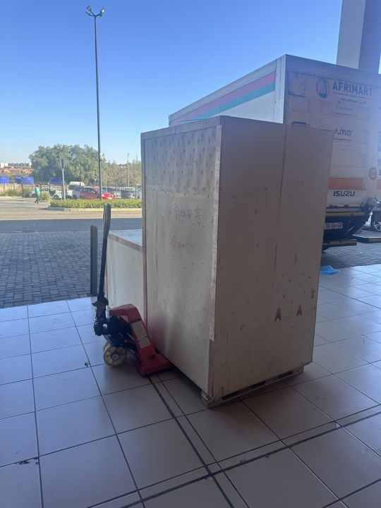
Loading
Toilet paper making machine
Toilet paper making machine
Toilet paper Rewinding Machine
latest arrivals

offloading
order success
order collection
order offloading