B21, China Town Mall, Midrand


2024 Railway Maintenance Plasser And Harsco Machine EL-T750ZS

- Section : Sports & Entertainment
- Category : Vehicle Parts & Accessories
- SKU : 1600440033801

- Product Overview
Railway Parts Railway transducers for the Railway Maintenance Plasser and Harsco Machine
Our roller type line displacement transducer is widely used in railway maintenance machinery, such as Plasser,Harsco,CRRC and other mainframe equipment.
FEATURES AT A GLANCE
Good compatibility
Products are widely used in railway maintenance machinery
Simple control, reliable performance and competitive price


PRODUCT SPECIFICATIONS
| No | Item | Data |
| 1 | Power voltage | +/-10vdc |
| 2 | Full Range | 780mm |
| 3 | Effective Range | +/-375mm |
| 4 | Signal ratio | 23.7mV/mm |
| 5 | Linearity | +/-0.2% |
| 6 | clearance error | less than 0.5mm |
| 7 | Operating Force | 2N--10N |

- Shipping Timeframes: All orders are processed within 2-5 business days (excluding weekends and holidays). After your order has been processed, the estimated delivery time is before 03 Aug, 2026, depending on customs, Please note that due to high demand, some items may experience longer shipping times, which will be communicated at order confirmation email.
- Order Processing Time: Please allow 2-5 business days for us to process your order before it is shipped . Orders placed after 16:00 on Fridays, or during weekends and public holidays, will begin processing on the next business day. Processing times may be extended during peak seasons or sales events.
- Manufacturing Time: Some products needs manufacturing time, the manufacturing process will take approximately 10-30 business days depending on the product. This timeframe may vary depending on the complexity of the product and current demand. but this will be communicated with you during order confirmation.
- Returns and Exchanges: We offer a 30-day return policy for most items. If you are not completely satisfied with your purchase, you may return it within 30 days of receipt for a refund or exchange. Items must be unused, in their original packaging, and accompanied by proof of purchase. Return shipping costs are the responsibility of the customer, unless the item was damaged or defective upon arrival.
1. What is the 2024 Railway Maintenance Plasser And Harsco Machine EL-T750ZS?
The EL-T750ZS is a roller-type line displacement transducer designed for railway maintenance machinery (e.g., Plasser, Harsco, CRRC). It measures linear displacement via a rolling contact and provides an electrical signal proportional to travel.
2. What are the key electrical and measurement specifications?
Power voltage: ±10 V DC. Full range: 780 mm. Effective range: ±375 mm. Signal ratio: 23.7 mV per mm. Linearity: ±0.2%. Clearance (backlash) error: less than 0.5 mm. Operating (actuation) force: 2 N to 10 N.
3. How do I convert the transducer output voltage to displacement?
Use the signal ratio: displacement (mm) = output change (mV) ÷ 23.7 mV/mm. Verify the sensor wiring and reference zero before measuring; if differential outputs or offset exist, consult the supplier datasheet.
4. What does 'effective range ±375 mm' mean compared to 'full range 780 mm'?
The listed full range is 780 mm (total travel). The effective range ±375 mm indicates the usable measurement span around the mechanical center (total usable = 750 mm). There is a small portion at each end of travel that may be outside the guaranteed linear/electrical specification—confirm exact usable limits with the manufacturer.
5. Is this transducer compatible with Plasser and Harsco equipment?
Yes — the product is specifically designed for wide compatibility with railway maintenance machinery including Plasser and Harsco equipment. For exact fit and integration (mounting, connector, and electrical interface) confirm model/part number compatibility with the OEM or supplier.
6. What mounting and mechanical considerations should I follow?
Mount securely to prevent play or misalignment. Ensure the roller contacts the measured surface with an actuation force within 2–10 N. Minimize mechanical clearance and backlash; the product specification lists clearance error under 0.5 mm. Protect the transducer from impacts and excessive side loads.
7. What are typical wiring and connector requirements?
The specification only states the power voltage as ±10 V DC. Connector type and pinout are not provided in the brief description—obtain the detailed datasheet or contact the supplier for wiring diagrams, connector type, shielding and grounding recommendations.
8. How should I install and align the roller for accurate readings?
Mount the transducer so the roller tracks smoothly on the target surface without binding. Ensure the roller axis is perpendicular to the travel direction and preload is within the 2–10 N range. Avoid sharp angles and maintain consistent contact throughout the measurement stroke.
9. What maintenance or care is required?
Keep the roller and measuring surface clean of debris, corrosion and heavy lubrication. Inspect mounting hardware and roller for wear periodically. Avoid impacts and excessive vibration. If drift or noise appears, check connections and mechanical alignment, and recalibrate as needed.
10. What troubleshooting steps should I take if readings are noisy or out of spec?
Check electrical connections, grounding and shielding. Verify the supply voltage is stable at ±10 V DC. Inspect the roller and mounting for mechanical binding or excessive play. Confirm the actuation force is within 2–10 N. If problems persist, request the full datasheet or contact the supplier for further diagnostics.
11. Can this transducer be customized for other ranges or connectors?
The product summary highlights good compatibility and competitive pricing but does not specify customization options. Contact the manufacturer or supplier to inquire about custom ranges, connectors, mounting configurations or special environmental protections.
12. What environmental and operating temperature limits apply?
The brief description does not list temperature or environmental ratings (e.g., IP protection). For operating temperature range, moisture and dust protection levels, request the full technical datasheet from the supplier.
13. How do I verify calibration and linearity?
Use a calibrated displacement standard to move the roller through the effective range and record the output. Compare measured output to expected displacement using 23.7 mV/mm; check that deviation stays within the specified linearity of ±0.2%. Recalibrate or service if tolerance is exceeded.
14. Where can I get spare parts, technical drawings or warranty information?
The product listing does not include spare-part numbers or warranty details. Contact your supplier or the manufacturer directly for parts availability, technical drawings, lead times and warranty terms.
Latest Order Arrivals
Discover our latest orders
12 Heads Embroidery Machine
Toilet Paper Machine Machine

Order Collection
Cross Border Clients
Order cros border countries Collected
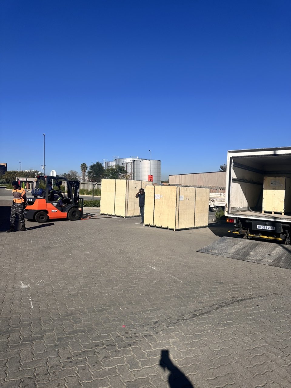
Industrial Machine Cllection
Agriculture Processing Machines

Ready for collection

Water Pump Equipment
Packaging Machine and accessories
Fabrics Manufacturing Equipment
Mining Equipments
Food Processing Machine
Batch of Orders
Batch of Orders
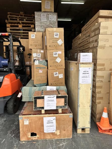
Latest Orders Labelled
wheel alignment machines
new arrivals
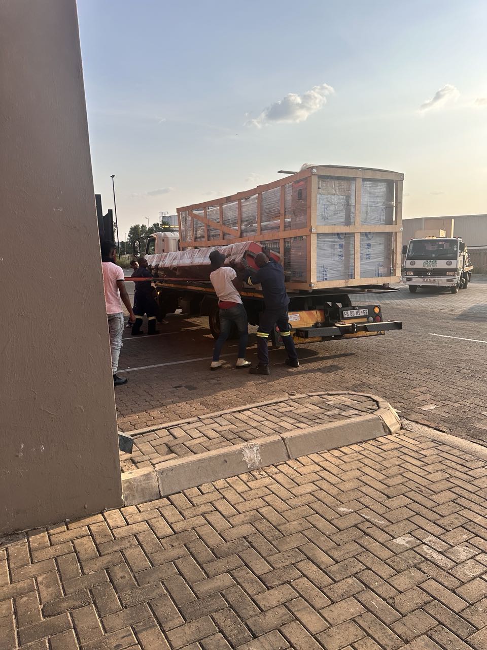
Pre Orders Offloading
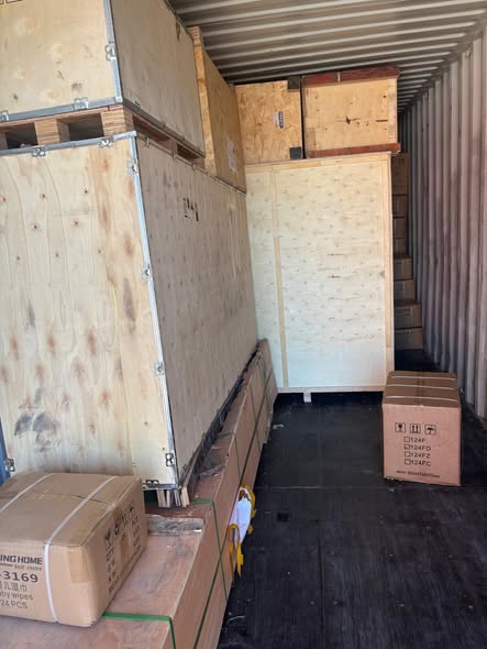
Latest Arrivals
Latest Arrivals
Latest Arrivals
Loading
Toilet paper making machine
Toilet paper making machine
Toilet paper Rewinding Machine
latest arrivals

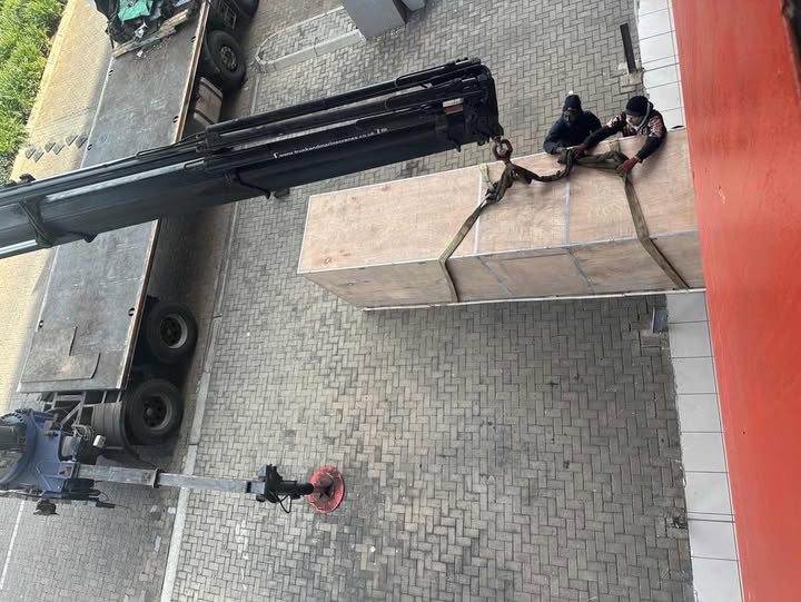
offloading
order success
order collection
order offloading